Special note : the following component values may be changed from printed overlays : C401, C402, R214 & VR1 (VR1 is not supplied). All kits shipped since early February 2004 include the LogMod components. Update/feedback please?
As of July 2004 there are three revisions (2, 3 & 4, there was no 1) of the WBo2 version 2A0 Printed Circuit Board (PCB).
|
PCB Revisions
|
Note : no performance improvements were made with the Rev-3/4 PCB.
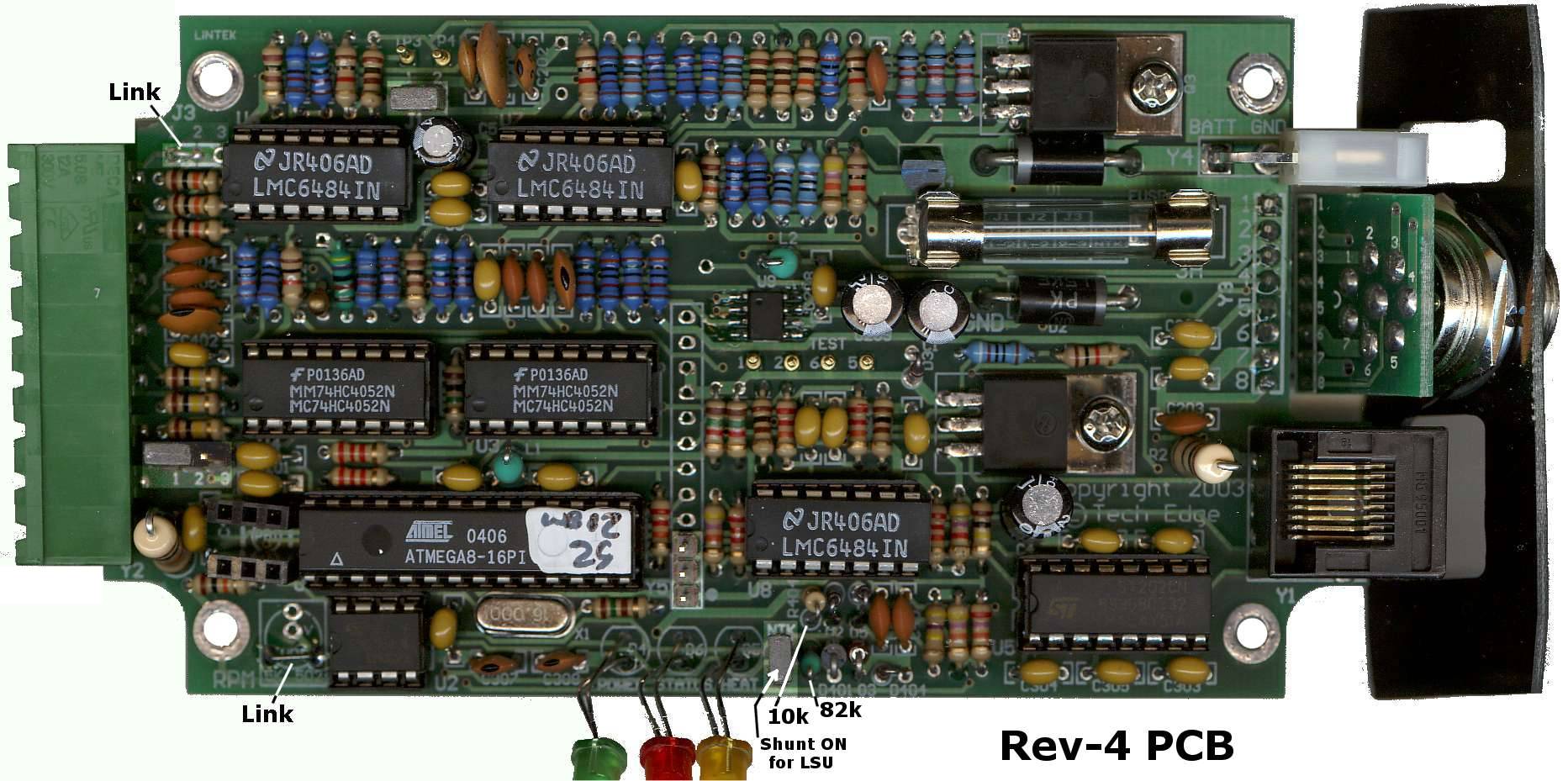
LSU/NTK support - Important WARNINGFor the Rev-2/3 PCB, support for the NTK sensor requires a change in value of R214 from 910 ohm to 82k ohm. It is very important that this change is made as damage to the NTK sensor will result if the 910 ohm resistor is used with the NTK sensor. Note also that the table under the fuse is WRONG and the PCB shunts/linkd should ALWAYS be set in the LSU position, & NEVER the NTK position. Remember to use the correct flash file if you change the hardware (ie. R214 or J-NTK's position, see below).Note that the Rev-4 PCB, instead of changing a resistor, has a jumper (labelled NTK beside the Amber/HEAT LED) which must be ON for the LSU, and OFF for the NTK. R214 in this case is 910R and an additional resistor RNTK (82k) is added. |
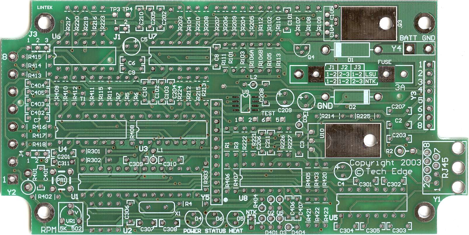
Rev-4 Silkscreen
|
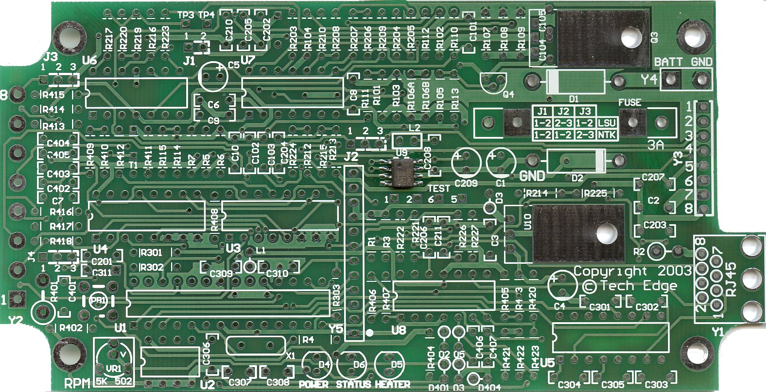
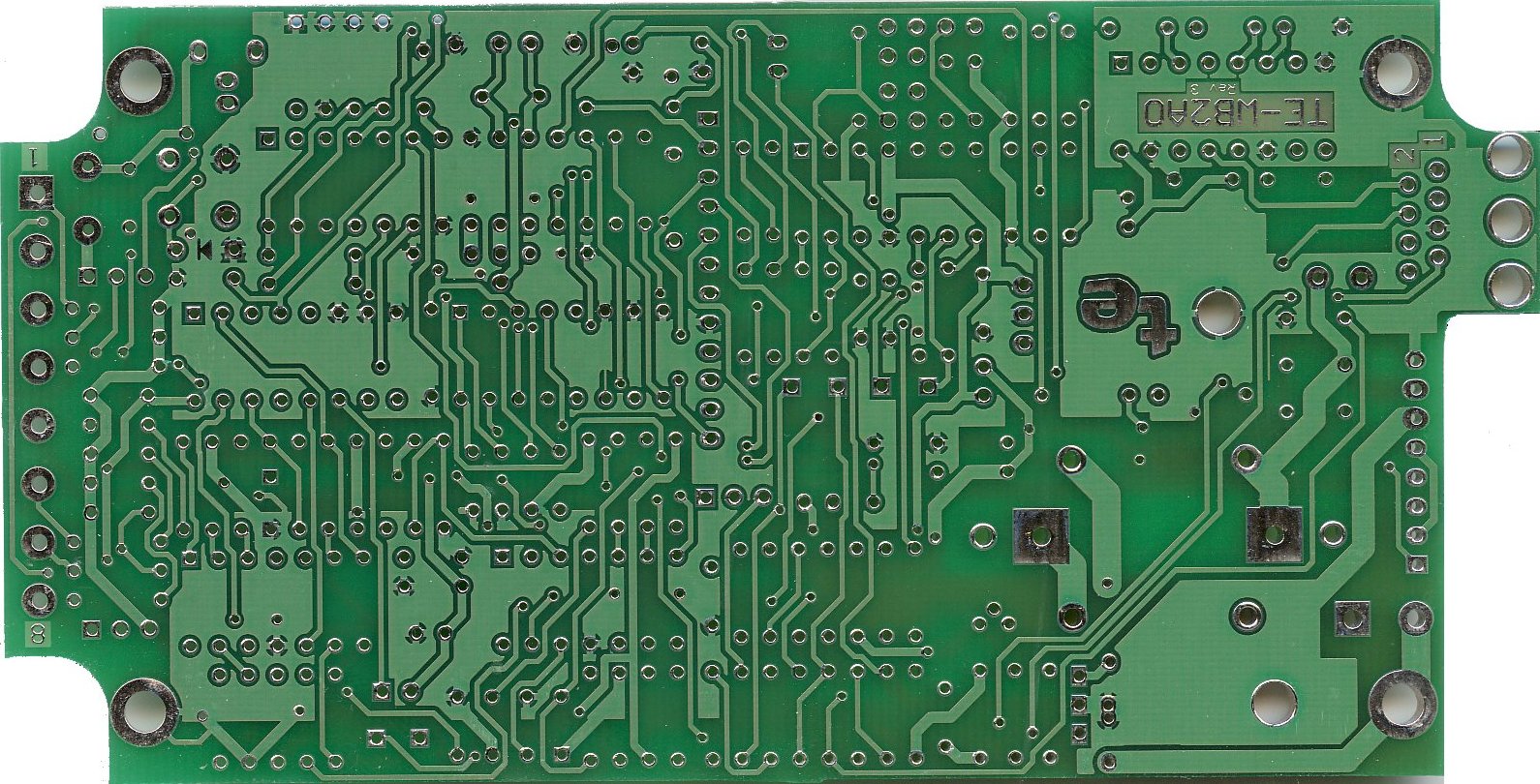
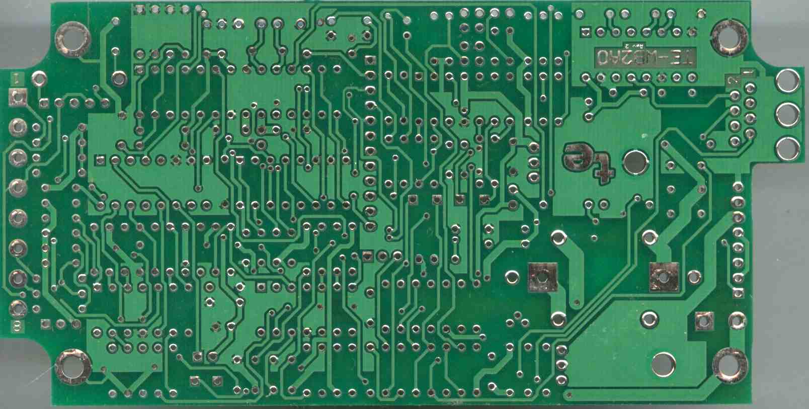
Top (component) & Bottom (solder) side images of the PCB
|
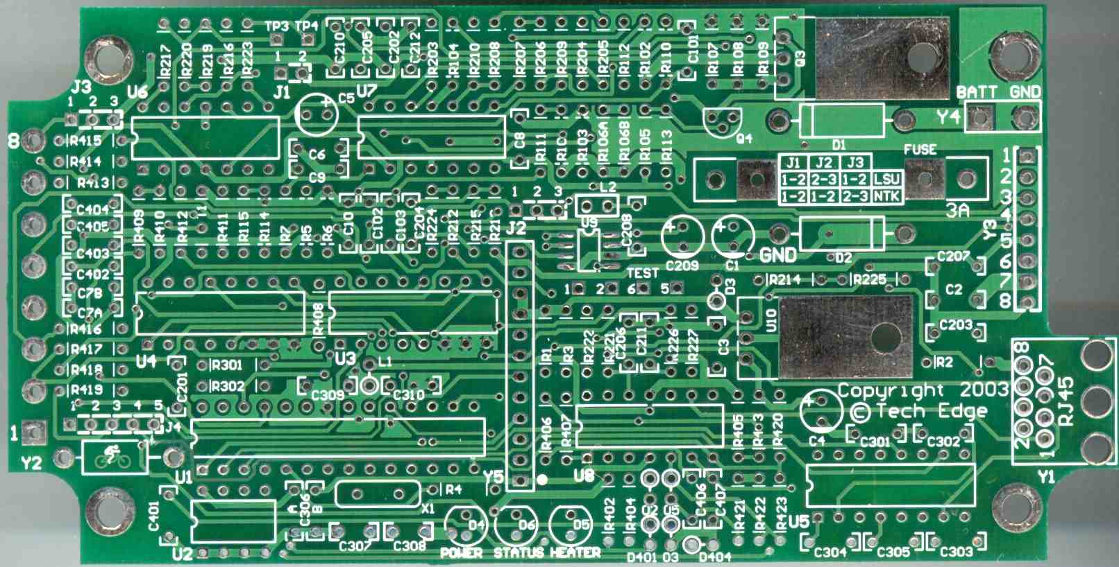
Actual Component Value OverlayThe Rev-4 image at right (click on it for a x4 enlargement) gives the actual component value of all parts to be placed on the Rev-4 PCB. Special NOTE : This overlay is slightly different to the actual silkscreen and correctly shows most 100R resistors as 5% (none need to be 1%, but we originally specified R205 as 1%, but a 1% here does not add to accuracy).Here's the Rev-3 enlargement. Use this overlay if you have the Rev-2 PCB. |
|
|
Designation OverlayThis is the Rev-4 overlaying showing the component designations (R22, C33, etc.) used on the PCB. (click on it for a x4 enlargement)Use this overlay if you have the Rev-3 PCB. Use this overlay if you have the Rev-2 PCB. |
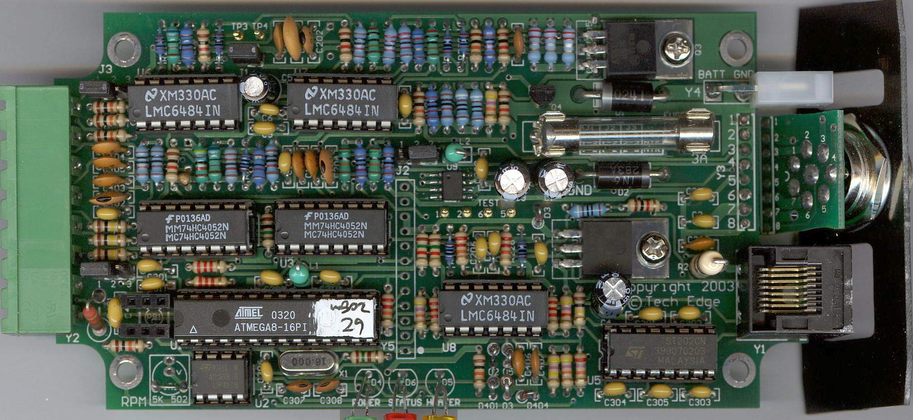
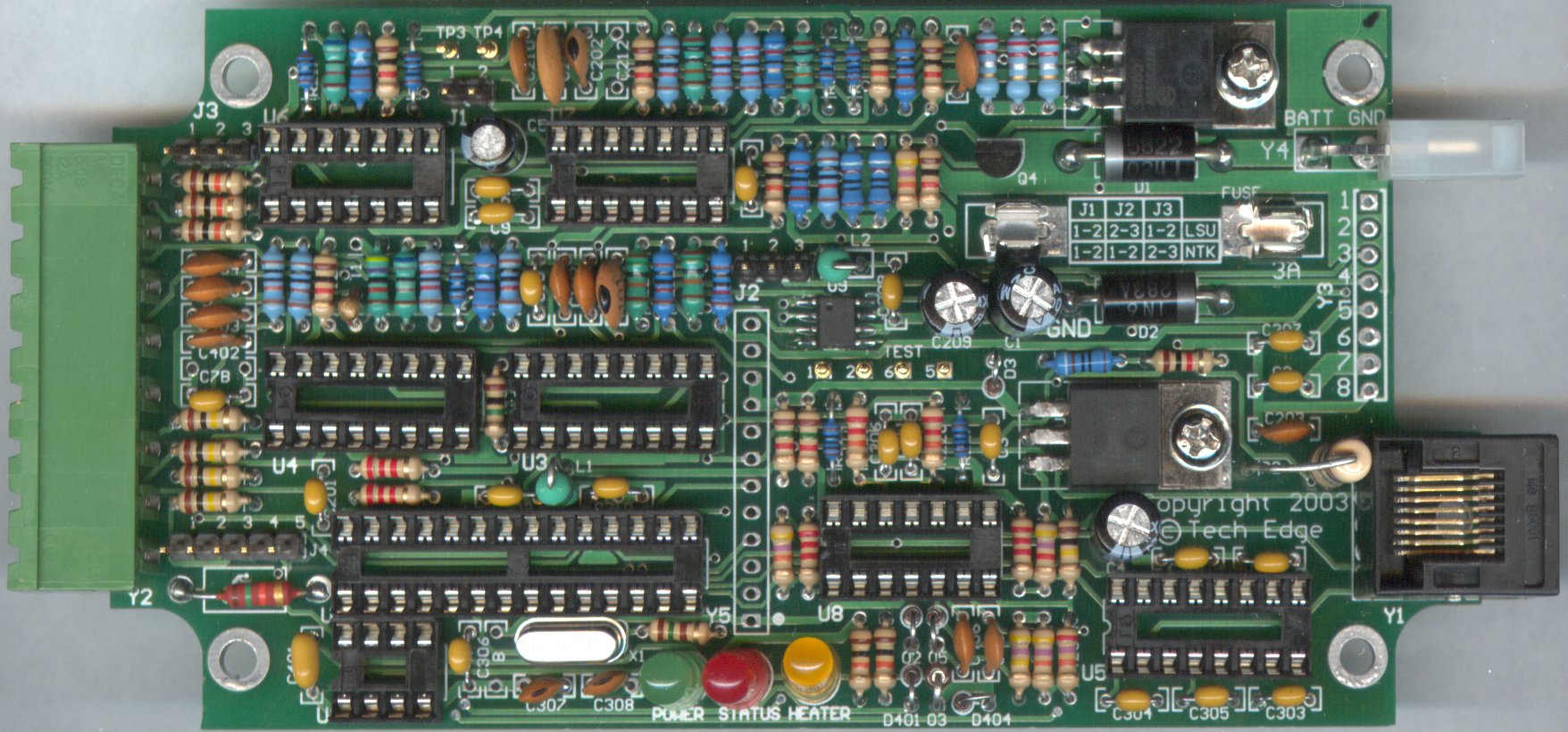
Constructed PCB imagesThese images should help you work out where all components go.Here's the Rev-4 PCB (230 kbyte) with most components soldered. Not shown is the detail of the logger button mounting scheme shown here. Here's the same information for the Rev-3 PCB (250 kbyte). Here's the original Rev-2 PCB (328 kbyte). |
|
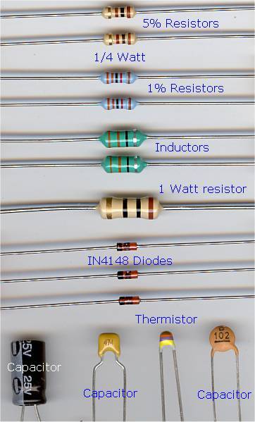 Click on the image to view some of the components that people sometimes have difficulty identifying.
These include the inductors, the thermistor, and the 1% and 5% resistors.
Note also that none of the 100 ohm resistors used in WBo2 need be any more accurate than 5%.
Click on the image to view some of the components that people sometimes have difficulty identifying.
These include the inductors, the thermistor, and the 1% and 5% resistors.
Note also that none of the 100 ohm resistors used in WBo2 need be any more accurate than 5%.
|
Resistors are shown in ohms and an R (=1), k (kilo=1000) or M (Mega=1,000,000) indicates both the multiplier and the position of the decimal point. Examples are :
| 100R | 100 ohms |
| 22k | 22 k ohms, or 22,000 ohms |
| 1M | 1 M ohms, or 1,000,000 ohms |
| 2M2 | 2.2 M ohms, or 2,200,00 ohms |
| 4R7 | 4.7 ohms |
| 0R22 | 0.22 ohms, or 220 milliohms |
Capacitors are measured in micro Farads (μ = greek mu = 10-6 F), nano Farads (n = nano = 10-9 F), and pico Farads (p = pico = 10-12 F). If the value is not clearly shown in μF then it will normally be measured in picro Farads (pF) in the form of vvm where vv is the value and m is the multiplier as a power of 10. Examples are :
| 47 μF | 47 micro Farads (clearly printed) |
| 100 | 10 picro farads (pF), 10 -> value, multiplier -> 0 |
| 471 | 470 picro farads (pF), 47 -> value, multiplier -> 1 |
| 474 | 47 0000 pico Farads (pF), or 470 nano Farads (nF), or 0.47 μF |
Other common values are : 105 = 1.0 μF (1000 nF, or 1,000,000 pF), 104 = 0.1 μF (100 nF, or 100,000 pF), 103 = 0.01 μF (10 nF, or 10,000 pF), 102 = 0.001 μF (1 nF or 1,000 pF), 101 = 0.0001 μF (100 pF), 100 = 0.00001 μF = (10 pF)
Resistors in beige or brown (generally) have a tolerance of 5%, and resistors in light blue or green have a tolerance of 1% and the two types should not be mixed. Capacitors are shown in μF (micro Farad), nF (nano Farad) and pF (Pico Farads).
Extra components for the older Rev 2 board are shown in orange. Some of these have been deleted or changed for the Rev 3 PCB.
Changes from the LSU (ie. the standard version) to the NTK version are shown in red italics Note that the only change is to R214 which is 910R for the standard (ie. LSU) version and 82k for the NTK version. It is also very important that an NTK sensor is not used on a standard version as damage to the NTK sensor will result. Note also that the firmware is different for the NTK and the LSU versions (see the re-flash software page for more information). D401 should now be an IN4007 but was oroginally specified as 1N4148.
| 1 | ATMega8 | U1 | Atmel AVR, with either LSU or NTK firware |
| 1 | M24256 | U2 | EEPROM (option) |
| 2 | 74HC4052 | U3, U4 | |
| 1 | ST202 | U5 | RS232 driver |
| 3 | LMC6484 | U6, U7 U8 | Op-amp |
| 1 | DAC7612 | U9 | DAC |
| 1 | 1N5822 | D1 | |
| 3 | 1N4148 | D402, D404, D405 | |
| 3/4 | 1N4148 | (D3), D402, D404, D405 | |
| 1/2 | 1N4007 | D401, (D3) | (D3 May be substituted with 1N4148 for rev-2) |
| 1 | 1.5KE-33A | D2 | |
| 1 | 1N4746 | D403 | |
| 1 | MTP3055V | Q3 | 12A 60V FET |
| 1 | 2N3904 | Q4 | GP NPN |
| 1 | 7805 | U10 | TO220 5V Regulator |
| 1 | 5mm LED | D4 | GREEN |
| 1 | 5mm LED | D5 | AMBER |
| 1 | 5mm LED | D6 | RED |
| 1 | 62R 1% | R206 |
| 1 | 100R 1% | R205 (may be 5%) |
| 3/2 | 910R 1% | R106A, R106B, R214 Rev-3 NTK version has R214 as 82k, Rev-4 adds 82k RNTK and J-NTK) |
| 1 | 1k0 1% | R410 |
| 3 | 10k 1% | R6, R103, R104, |
| 1 | 12k 1% | R114 |
| 2 | 15k 1% | R5, R219 |
| 2 | 22k 1% | R207, R208 |
| 4 | 30k 1% | R101, R102, R212, R213 |
| 1 | 47k 1% | R411 |
| 2 | 68k 1% | R220, R115 |
| 1 | 82k 1% | RNTK (Rev-4), R214 (for Rev-3 PCB with L1H1. Note : For LSU use R214=910 ohms) |
| 1 | 100k 1% | R409 |
| 2 | 150k 1% | R215, R224 |
| 2 | 200k 1% | R209, R210 |
| 3 | 0R22 5% | R107, R108, R109 |
| 6 | 100R 5% | R7, R204, R217, R222, R223, R227 (may be 1% in some kits) |
| 1 | 150R 5% | R4 |
| 6 | 1k0 5% | R110, R113, R203, R216, R225, R412 |
| 2 | 1k5 5% | R1, R3 |
| 4 | 2k2 5% | R301, R302, R405, R407, |
| 1 | 4k7 5% | R403 |
| 7 | 10k 5% | R111, R112, R402, R404, R413, R414, R415 |
| 3 | 22k 5% | R221, R226, R303 |
| 1 | 27k 5% | R423 |
| 3 | 47k 5% | R105, R406, R422 |
| 4 | 100k 5% | R416, R417, R418, R420 |
| 1 | 100k 5% | R419 |
| 1 | 470k 5% | R421 |
| 1 | 1M 5% | R408 |
| 1 | 10R 1W 5% | R2 |
| 1 | 15k 1W 5% | R401 |
| 2 | 15pF | C307, C308 |
| 1 | 22pF | C202 |
| 2 | 100pF | C204, C402 |
| 1 | 560pF | C205 |
| 7 | 1nF | C102, C103, C203, C403, C404, C405, C406 |
| 1 | 3n3 | C210 |
| 2 | 10nF | C101, C407 |
| 1 | 470nF | C401 |
| 23 | 100nF | C2, C3, C6, C7A, C8, C9, C10, C201, C206, C207, C208, C211, C301, C302, C303, C304, C305, C306A, C309, C310, C311, SNUB1/C104, SNUB2/C105 |
| 1 | 47μF | C5 |
| 3 | 100μF | C1, C4, C209 |
| 3 | Not Installed | C212, C7B, C306B |
| 1 | 8 PIN | U2 | |
| 3 | 14 PIN | U6, U7, U8 | |
| 3 | 16 PIN | U3, U4, U5 | |
| 1 | 28 PIN | U1 | |
| 2 | FUSEHDR | FUSE | FUSE HOLDER |
| 1 | RJ45 | Y1 |
| 1 | 8 pin green in-line plug | Y2-M male PCB mount |
| 1 | 8 pin green in-line screw terminal socket | Y2-F mating female part |
| 1 | 8 pin circular connector | Y3 |
| 1 | DB9 female socket | |
| 1 | DB9 backshell kit with mounting bolts | |
| 1 | 2 pin MOLEX 90� right angle PCB mount | Y4 |
| 1 | 2 Pin MOLEX plug | mates with Y4 |
| 2 | 2 MOLEX terminals | pins for Y4 |
| 1 | 13 Pin HEADER (J1 to J4, cut 2+3+3+3) | (Rev-2 J4 = 5 pins) |
| 1 | main PCB | TE-WB2A0 (SOIC chip U9 pre-installed) | |
| 1 | small PCB | transitional PCB for Y3 | |
| 2 | 10mH | L1, L2 | Inductor |
| 1 | 47K @ 25�C | T1 | Thermistor |
| 1 | 16MHz | X1 | CRYSTAL |
| 1 | 3AG 3A | FUSE | |
| 1 | PB1 | Switch | Press Button |
| 1 | Grey ABS Plastic case (top & Bottom, rubber feet and 4 screws) |
| 2 | case ends (screen printed) |
| 6 | M3 bolts (4 for PCB to case, 2 for TO220 to PCB) |
| 2 | M3 nuts (for TO220 to PCB) |
| 8 | M3 star washers (4 for PCB to case, 2 for TO220 to PCB) |
| 6 | Gold plated test-point pins (TP1 to TP6) |
| 4 | Shunts (for J1 to J4) |
| 1 | Cable tie (for anchoring DB9 wires to shell) |
| 1 | 2 m figure 8 power cable |
| 1 | 50 cm two core grey cable with moulded RJ45 end (part of RS232 cable) |
C401 was originally specified as 470nF but some applications, particularly multi cylinder or high revving engines may require this value to be reduced to as low as 100nF. The Rev-3/4 PCB has the option of a 5k preset pot VR1 that was added over the Rev-2 PCB. Normally VR1 is bypassed with the VR1 wire link but VR1 can be installed and may improve RPM pickup performance for some applications. VR1 is not supplied in kits.
The Rev-4 PCB cleans up the redundant J2 but adds a jumper and resistor to allow easier changing between NTK and Bosch sensors. Note that the silkscreen under the fuse is WRONG and the shunt/link positions should be always be set in the LSU position. All Rev-4 PCBs are now 100% bare board tested (BBT).
Jumper J-2 completely removed from the PCB. The now spare J-2 pins in the kit can now be used in the 2-3 position of Y-5 (or the now spare J-3 in the 1-2-3 position if you change J-3 to a wire link, see below) to act as a possible Rescue Re-flash header (refer to the Flash Upgrade page). Note that normally NO shunt is used on Y-5.
Jumper J-NTK has been added (beside Amber/HEAT LED). Note : the NTK shunt is OFF for the NTK, and ON for the LSU.
RNTK (82k 1%) has been added (beside J-NTK). Note that R214 is always 910 Ohms on Rev-4 (does not change if you use the NTK sensor).
J-3 has been replaced with a wire link and the 3 pin header may be used in the 1-2-3 pin position (at the bottom) of Y5 (this allows easier reflashing by bridging 2-3 of Y5)
Parts list and overlay (but not the silkscreen on the PCB) changed so all 100R resistors are 5%, if you have any 1% 100R in your kit then use one for R205 (but this is not an accuracy issue at all).
The Rev-3 PCB adds a press button switch to control on-board logging. Note : This functionality can also be added to the Rev-2 PCB. Note that the silkscreen under the fuse is WRONG and the shunt/link positions should be always be set in the LSU position.
R401 15 k 1W is now positioned vertically.
R2 10 R 1W is now positioned vertically (space needed for PB1).
J4 is now a 3 position header 1-2 = COIL (as before), 2-3 = RPM-LO (as 4-5)
C104 and C105 (aka SNUB1 & SNUB2) now have their own solder pads on the bottom of the PCB (insert from the bottom of the PCB before attaching the MTP3055 FET)
R419, C7A, C306A, C212 all removed from the silkscreen.
Fixes to the PCB include :
Y5-p8 is now GND.
the SCK and SD lines to the serial EEPROM have been reversed.
The additional trace to the processor's reset pin has been removed.
Components PB1 and R303 (22k 5%) added for controlling on-board logging.
Optional additional components C311 and 6V Zener (on back of PCB) added for remote logging switch support only (these parts are not included in the DIY kit).
Optional additional components VR1 added (and C401 may need changing) to control RPM limiting (see above).
Changed C402 from 10 nF (103) to 100 pF (101) (thermocouple amp change - 27-Oct-03)
From firmware rev 0029, WBo2 supports on-board logging using a 32 kbyte serial EEPROM. The button starts and stops logging, and controls playback. The Rev-3/4 PCB actually has the press button holes on the PCB, but the Rev-2 PCB can add the same functionality almost as easily. See the WBo2 Logging Info. and Specs. page for more information.
We appreciate your feedback on the content and any corrections necessary to this article.