Note :This information relates to the 2C0 pre-production prototype unit We released strictly limited quantities of this unit for sale in December 2004. It utilises an SMD PCB we were trialing. In general these units have been reliable and we sold them at a good price to both promote them and in case we later found some production problem with them. Go here for the updated and Current 2C0 production unit.
We have retained this information to support those customers who have this model, which is identified by having a circular (DIN) connector at one end.
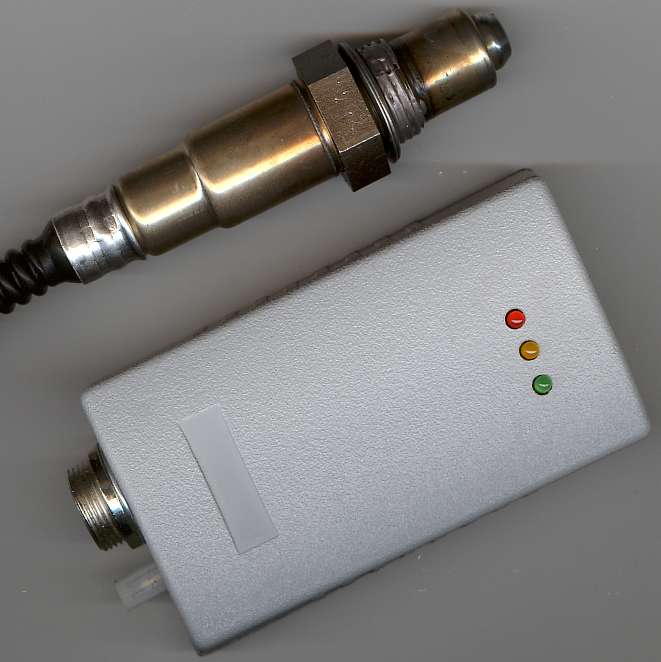
The Tech Edge 2C0 pre-production prototype Wideband unit is housed in a tough ABS plastic case. As you can see (click on the image for a x3 or here for x3 popup) it's small at 90 x 50 mm (credit card size) and 25 mm high. To get the unit to this size we had to leave the analogue input channel logging features out. Many ECUs now have inbuilt logging so it didn't seem too much of a restriction. Note : The production version will have RPM logging. The unit has 4 connectors that go to :
|
The following information relates to the pre-production (small run prototype run) of the 2C0 unit. The full-production unit will use different connectors, namely an 8 pin RJ45, a 6 pin RJ11, and a 6 pin removable (green plug-in screw-on) connector located along the side of the unit. Full details of that version will appear when the production version is released.
2C0 Outputs (pre-production unit)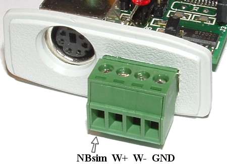
Green 4 pin Connector OutputsThese 2C0 units have a 4 pin green output signal connector at one end of the unit. This screw in block can be readily removed from the unit for maintenance. The output pins are assigned as show in the image at left. Note : W is short for WBlin :
The WBlin & NBsim output signals can both be re-programmed using the CONF Utility. |
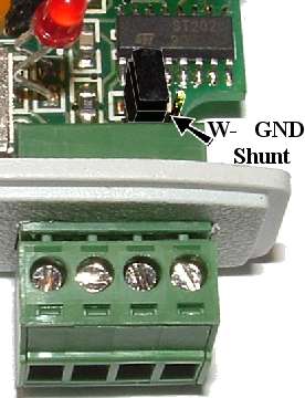
Differential WBlin Output ConsiderationsThe WBlin+ and WBlin- (shown as W+ & W- in the image above) are the floating (or differential) WBlin outputs. They are provided because many devices WBlin will be used with have only a single ended input with a common equipment GND. For further information, refer to WBlin+/- Explanation and Information page. The image at right shows the location of the WBlin-GND shunt (called W- in this image). |

|
The circular 6 pin mini DIN connector, shown at left with pin number assignments, carries :
The mini DIN connections are as viewed from the end of the case (as in the images above - see popup). This view is also the same from the back of the mating male connector where you would solder wires to. At right is shown how the mini DIN should be wired to a female DB9 connector for connection to a PC. Note that the designation Rx & Tx relate to receive and transmit as seen by the 2C0 unit itself. A PC would connect the 2C0's Tx to its own Rx input. |
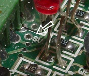
SVout Output (Internal Pin)As with other WBo2 units, 2C0 has an SVout output (which can be use with the LD01 display). SVout is not available on any external connector, but it is available within the unit. It is right behind where the green 4 pin connector meets the mini-DIN connector. Refer to the image - the arrow points to this area. The PCB has an SV symbol right beside the larger hole in the PCB. 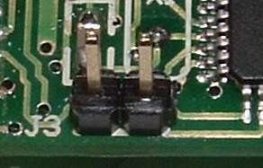
Rescue Re-Flash J3Like other WBo2 units, the 2C0 unit's program memory can be field upgraded. This is normally done using the Flash utility. J3 is the Rescue Re-flash jumper. In some unusual situations it's possible to erase the unit's program memory. The J3 jumper should only be used to rescue the unit when the normal software re-flashing has failed. J3 is located close to the large 44 pin ATMEGA16 chip shown at right. Note: temporarily use the J1 shunt (which should always be ON) when you need to rescue re-flash the 2C0 unit. |
)
)