Y3 Connector
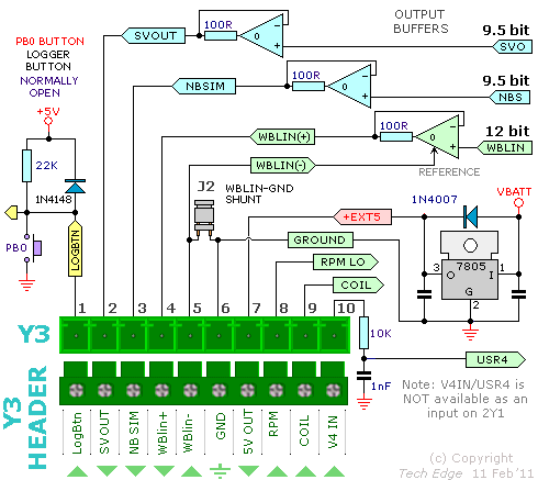
Front side of 2Y, 10 pin connector (3.81mm pitch).

notes:
- The WBlin-GND jumper-shunt J2 is described in detail here.
An external wire link between Y3 pin-5 and Y3 pin-6 may be used in place of J2.
- The three outputs WBlin, SVout and NBsim outputs are fully independent
and their Voltage/Lambda output curve can be 100% re-programmed with
WButil's output programming function.
- The V4 IN input cannot be used as a 7th input. It is intended to be used as the only analog input
if a simplified version of 2Y is built without end connector Y2.
- The external logger button circuitry duplicates the function of the PB0 button.
- The Y1B RJ45 socket duplicates the Y1A socket at the right end of the case.

Y2 Connector
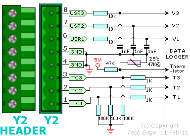
Left end of 2Y 8 pin connector (5.08mm pitch).

notes:
- The Y2 connector is numbered counter intuitively from right to left.
- The thermistor T1 is shown here because it is physically close to the connector (so as to be close in temperature).

Y1A, Y5 & Y4 Connectors
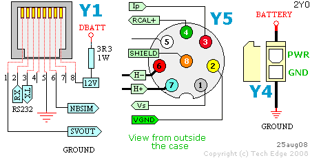
Right end of 2Y RJ45, Circular 8-pin, Molex™ 2-pin.

notes:
- The Y1A RJ45 socket duplicates the Y1B socket at front side of the case.