LSU (5 Wire + RCal) PinoutsAll LSU sensors we have seen, regardless of the connector, use the five lead colours shown in the image below (Red, Yellow, Grey, Black, White). The laser trimmed calibration resistor (Rcal) is unique to each sensor and adds a sixth pin to the connector. Each sensor's Rcal (shown as 30-300Ω) has a unique value that only works properly with that sensor. Rcal connects internally to the Pump Current (Ip) sensor lead. |
|
| ||||||||||||||||||||||||||||||||||||||||||||||||||||||||||||||||
The sensor-connector (ie. the connector that comes with the LSU sensor) mates with the harness-connector. Tech Edge sells ONLY the harness-connector end, NOT the sensor end!. In general the sensor end is NOT commercially available.
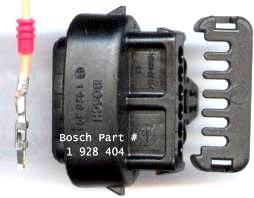
For people making or modifying cables, it's very important that you check the connector numbering scheme which seems to have a different scheme from one connector to the next (compare the 7057 and the 17025 numbering). Tech Edge has used the following LSU sensors with various WBo2 units. Images below show the 6 pin connector (with Rcal) attached to the sensor. Go here for information on LSU connector kits available. Click on the images to get larger images of the sensor connectors.
| Click connector images to enlarge | Sensor Connector |
Sensor Pinouts - |
|---|---|---|
|
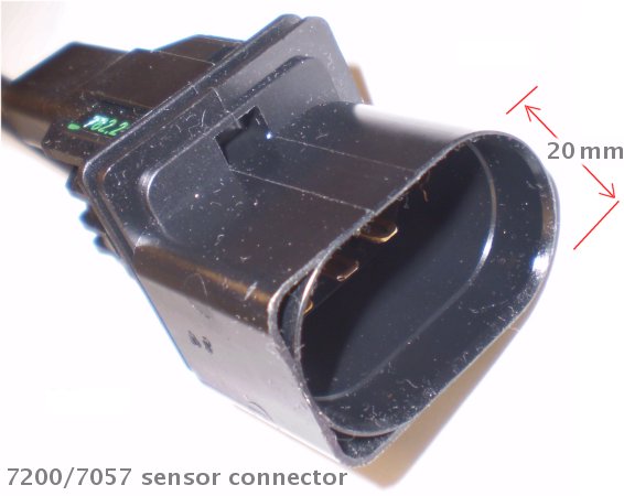
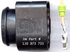
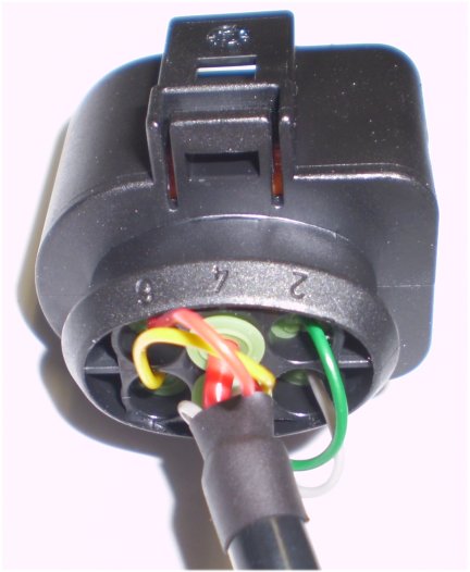
7200 or 7057 are LSU 4.2 sensors.
Full part number is 0 258 007 7200. Sensor connector is shown looking at the mating face. Note that the green pin is from the RCal part inside the sensor connector housing, and thus there's no green wire to the sensor assembly (represent by the blue area to the right). |
|
|
6066 is an LSU 4.0 sensor.
Bosch number is 0 258 006 066. Controllers must be recalibrated if changing between LSU 4.0 and 4.2 sensors. |
|
|
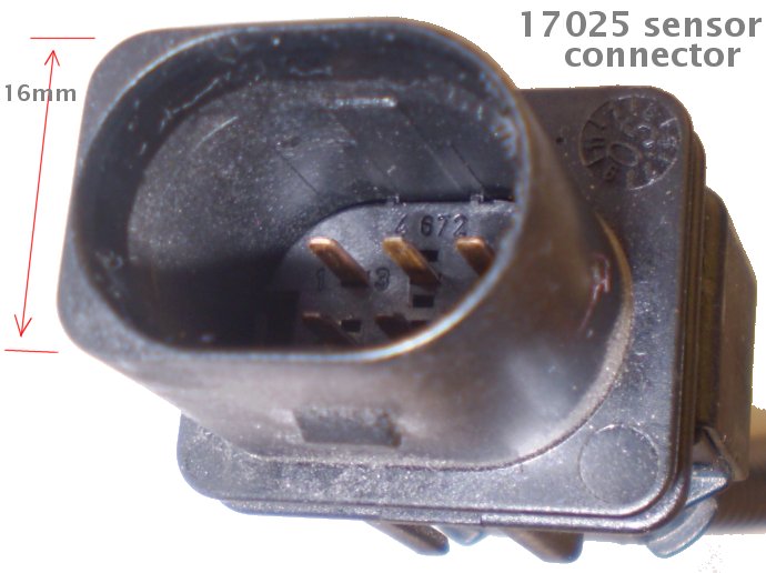
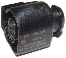
17025 is an LSU 4.9 sensor.
Bosch number is 0 258 017 025. The 4.9 sensor is very different to the 4.0/4.2 and also requires a bias current. Controller jumpers and firmware must be changed between LSU 4.0/4.2 and 4.9 sensors. Note also that the pin numbering changes but positions remain the same for the 4.2 and 4.9 connectors! |
|
Please refer to the LSU page for information on available LSU sensors that work with WBo2. Note : The Terminals and end seals are also available as AMP/Tyco parts but we are unable to provide more information (contact AMP/Tyco direct).
| LSU part # |
Mating (Harness) Connector |
Mating Connector Pinout |
|
|---|---|---|---|
|
Mating Sensor
|
|
Tech Edge part # [CNK7200]
|
|
|
Mating Sensor
|
|
Tech Edge part # [CNK17025]
|
|
|
Mating Sensor
|
|
Tech Edge part # [CNK6066]
|
|
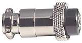
Circular 8 Pin Connector as Used on Cables
Along with recent cable changes, we have also changed our connector supplier and there are now a couple of small variants in the circular 8-pin connector used in our cables. In general this will not be an issue unless you come to repair your cable. 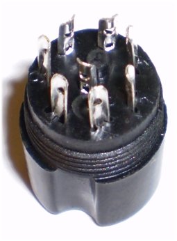
The sensor end of the cable is attached to the mating or harness connector. These connectors are described above. The following section describes all cables we have manufactured, including old and new styles, for the 7057/7200, 6066 and 17025 sensors. |
|
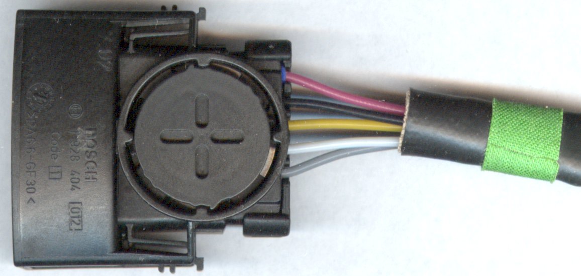
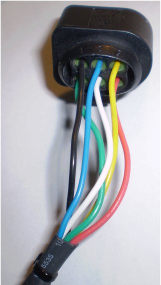
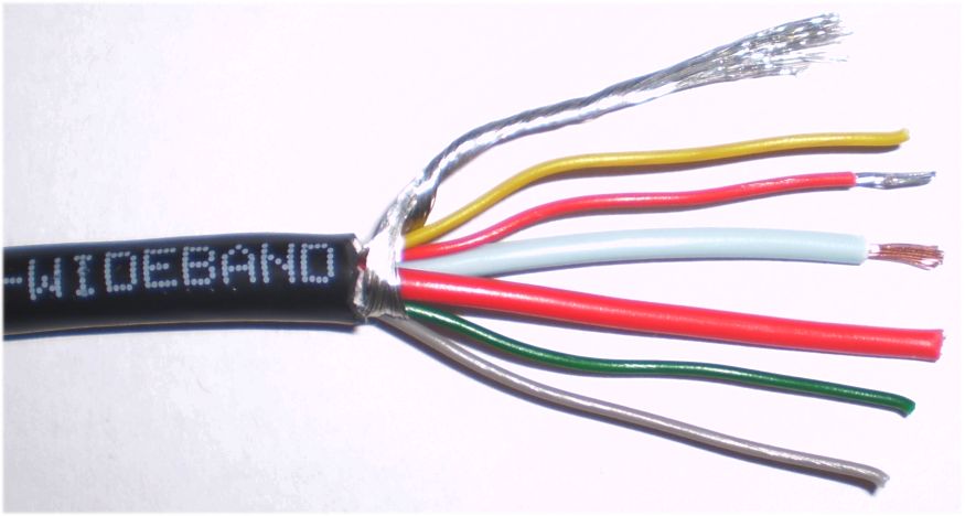
7200/7057 (LSU 4.2) "New" Cable Note that the shield is an integral part of the design and should ONLY be connected at the 8 pin (controller) end to GND. Click to enlarge the image. |
|

|
17 025 (LSU 4.9) "New" Cable The 17 025 connector is similar (but smaller) to the 7057/7200 (they have the same wire colour layout), but the connectors are numbered differently (refer to the table). Click to enlarge the image. |
|
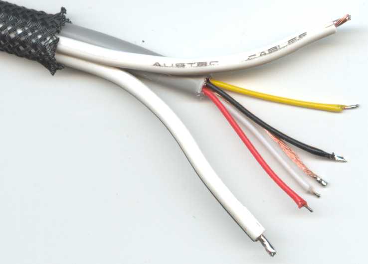
6066 (LSU 4.0) "New" Cable The internal wiring in the 6066 cable is shown as well as the coloured end wires going to the harness connector and the LSU sensor wires too. (Click to enlarge it). |
|
|
7200/7057 (LSU 4.2) "Old" Cable The 7 057 & 7200 cables are similar. Click to enlarge the image. |
|
17 025 (LSU 4.9) "Old" Cable The 17 025 cable is similar to the 7057/7200 (they look the same from the back of the connector), The connectors have different pin numbering (refer to table). Click to enlarge the image. |
|
|
6066 (LSU 4.0) "Old" Cable The 6066 is the oldest of the sensors on this page. (Click to enlarge it). |
Go here for more info on LSU sensors, here for connector kits sold, and here for DIY cable construction.
 In mid 2007 Tech Edge improved the way it manufactures cables.
They should now be more reliable, stronger, and less prone to damage through flexing in the middle and at either end.
In mid 2007 Tech Edge improved the way it manufactures cables.
They should now be more reliable, stronger, and less prone to damage through flexing in the middle and at either end.

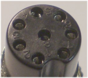
 New (One Part) Cable : This diagram shows both the front of the circular 8-pin connector as seen by someone looking at the end of the completed cable,
and also the wire or solder-side end of the connector that will be seen during construction or repair.
Note that the shield (braid) is connected to the centre (pin 8), but at the sensor end of the cable, the braid is left unconnected -
thus the braid acts as a
New (One Part) Cable : This diagram shows both the front of the circular 8-pin connector as seen by someone looking at the end of the completed cable,
and also the wire or solder-side end of the connector that will be seen during construction or repair.
Note that the shield (braid) is connected to the centre (pin 8), but at the sensor end of the cable, the braid is left unconnected -
thus the braid acts as a  Old (Original Two Part) Cable : This diagram shows the corresponding two part (older or original design) cable.
All the signal wires are carried in a cable with four individually shielded small wires.
The Heater current is carried in a separate heavy duty figure-8 cable that goes to pins 6 & 7
Note : the heater wire with tracer colour goes to pin 7.
Old (Original Two Part) Cable : This diagram shows the corresponding two part (older or original design) cable.
All the signal wires are carried in a cable with four individually shielded small wires.
The Heater current is carried in a separate heavy duty figure-8 cable that goes to pins 6 & 7
Note : the heater wire with tracer colour goes to pin 7.