
Updated Re-flash Utility here!
Information on the old unsupported utility follows
|
This utility (FLASH.exe) upgrades both WBo2 & LD02's code/program or flash memory as well as EEPROM data memory. This is normally only necessary when new features or fixes are released. See the this page for the latest WBo2, AL1 & LD02 flash (.HXF files) available.
|
LA1/LD02 Note : The procedure for re-flashing LA1 and LD02 is slightly different to WBo2 and is described in detail below.
Screen - Brief DescriptionThe FLASH utility screen shown at left is described briefly here and in detail in sections below. At the top we see the Title Bar showing the utility's software reversion number (2.1a in this case). Below right is the Com Port area where the port used to talk to the WB unit must be selected. If a green circle is shown then the utility thinks the WB unit is attached. At right is the Dialogue Info text box showing commands to the WB unit (x0 in this case) surrounded by [braces], and returned data prefixed with a > (data is 0E08). Further below is where the name of the Flash File is entered manually, by dragging and dropping, or browsed for using the File ... button. Various Flash Options can be selected before the Start button sends the file to the WB unit. The Status Info area shows different information related to the task being performed and details about the file just read a shown here. Other status information is shown as the files is being flashed. Lastly, the area at the bottom of the display shows, to the left ,error and status messages, and the circled area at the right if for sending raw commands to the wideband unit when it is not being flashed. Command results are shown in the dialogue info area at top right. |
The COM port that WBo2 is connected to must be selected from the drop down list in the COM Port frame. If any comms activity is detected, the circle will change to green. The Comms/Data text box displays data received from WBo2 during the course of executing command, and provides debug information. The flash file, with extension .HXF, is selected in the Flash File text box. A file can be dragged and dropped into the text box, or the File ... button will produce a dialog box to select the file. The file is read and checked as soon as it is selected. The ROM Ver. area indicates the current firmware detected when the COM port connected to WBo2 is first opened. The following options can be selected :
The Start button does just that, checking that the file and COM ports have been set up. |
The Abort button only becomes active during re-flashing and is only provided for the rare situation where WBo2 or your PC hangs during re-flashing. A series of pop-up error messages will normally be displayed when Abort is activated. You may then need to select the Rescue? option and try again. The image at left shows the display after both the COM port has been opened and the flash file has been selected. Other things to notice are the Progress/Status text box displays the results of opening the file. The Status area shows that COM1 has been opened. The bottom right corner also displays this utility's revision information. Re-flash ProcedureBegin by first connecting WBo2 to your Windows PC (Win95 or greater required). The short serial cable is used for the connection. Start the utility and then select the correct COM port. If you have just one available COM port then this will be done automatically. Then select the flash file (will normally have a .hxf extension). If you have a display like the one at left then you're all set to press the Start button. If you have not selected the Rescue? option then you should see a display of the following form ... |
As each block of flash memory is downloaded and successfully programmed, an acknowledgement is displayed as shown. The status display shows the text Programming Flash .... Sometimes a block may not be received correctly or may need to be re-programmed, in this case the display may pause briefly and rather than the =!=, a ??? will be displayed.
|
At completion of the flash and EEPROM programming the message box Programming Complete pops up. The total number of retries for both flash and EEPROM are shown in the message. After clicking on the OK button that's all that has to be done. Note that the ROM Ver. field (see above) will be updated with the current version of the reflashed file. |
Rescue Re-flash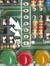
There will be times when the software re-flash method will not work. An alternative, the rescue re-flash method, is available when there is :
Although often "saving the day", rescue re-flash will only work when the processor still retains its (hardware write protected) boot loader code. If this small section of code has become corrupt too, then the only recourse will be to replace the processor (if it has a DIP socket) or return the whole unit to have it factory reprogrammed. Unfortunately, even if you have the capability, it is not possible to obtain a copy of the bootloader in a attempt to reprogram the processor yourself. Procedure : Inside WBo2 a jumper must be temporarily inserted. When the power is re-applied, the built in firmware bootloader checks for the jumper and then executes the re-flash software download under control of the re-flash utility. Each Wbo2 unit has its rescue re-flash jumper in a different position, so it is important to know where to find them. The image at right is for the 2A0 unit (rev-2 PCB) (other units are listed below). It shows the two pins (2 & 3) of Y5 that must be bridged whilst power is first applied to the WB unit (It is only required for just that time). Y5 is located above the 3 LEDs and most WBo2 units will not have a header there, just a row of holes in the PCB. A thin paper clip serves as a good jumper, but be careful NOT to short it against the legs of the adjacent LEDs. Note : most Rev-3 and up 2A0 PCBs were shipped with a three pin header in Y5 positions 1-2-3. Here are the locations of other WBo2 unit's jumpers, but note that in some cases a jumper must be moved from one pin to an adjacent pin, or a spare jumper found (or another jumper temporarily moved) : 2A0 (Y2 2-3), | 2B0 (J2 2-3), | 2C0 (J3 ON), | 2D0 (J1 ON), | 2E0 (J2 ON) | See below for LD02 [J1 ON] and LA1 [TBA]. |
|
Force Re-Flash Points to NOTEThe Rescue? option must be checked, and preferably the WB sensor cable unplugged from the WB unit, before the Start button is pressed. A message box then tells you that you must do the following :
The reflash should now proceed as normal. |
Here are the steps to get the WBo2 Re-flash utility installation files.

|
See the HXF file page.
|
As shown in the image, to enter config mode press LD02's top button or LA1 left (A) button while power is being applied. The firmware will detect this and go to config mode rather than display mode. In config mode the 4 digit firmware version will be displayed. In config mode the flash utility can start the download process for code memory (ie. flash program) which will complete in just a few seconds. LA1/LD02 will then be commanded to reset itself, during which time the top (or left) button must be held down for the EEPROM programming stage to now complete. 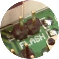
If this second stage is missed then the simplest thing to do is to abort the EEPROM programming step (press the Flash utility's Abort button then the Cancel button when the error message pops up) and again put LA1/LD02 in config mode, but this time select the EE Only? option. Note that at this stage, if an error message about version 0022 and using the rescue option pops up, then either LA1/LD02 is not in config mode, or the main flash did not work. If necessary, LA1/LD02 Rescue Re-flash is achieved in the same way as for WBo2. The image at left shows rescue re-flash jumper J1 for LD02 located to the right of the LEDs and left of the top button, and clearly labelled FLASH. When instructed, turn LD02 off, put the flash jumper on, press the OK button and turn LD02 back on. As before, you also need to press the top button to ensure LD02 reboots in config mode to program EE memory. |
 While the flash programs in a few seconds, the EEPROM takes a minute
or so to program and a similar time to verify.
The display for the programming and the verification steps is shown at left.
The programming steps shows the address to be programmed,
but the verify shows the data programmed (as a 4 digit hex value).
While the flash programs in a few seconds, the EEPROM takes a minute
or so to program and a similar time to verify.
The display for the programming and the verification steps is shown at left.
The programming steps shows the address to be programmed,
but the verify shows the data programmed (as a 4 digit hex value).
 Reflashing LA1 or LD02 is essentially the same procedure as for WBo2 except for the
important difference that displays must first be put into config mode
where it can respond to commands from the flash utility.
(normally, LA1/LD02 will just look for data from WBo2).
As well, LA1/LD02 is reprogrammed using the reprogramming adapter (shown as a popup
Reflashing LA1 or LD02 is essentially the same procedure as for WBo2 except for the
important difference that displays must first be put into config mode
where it can respond to commands from the flash utility.
(normally, LA1/LD02 will just look for data from WBo2).
As well, LA1/LD02 is reprogrammed using the reprogramming adapter (shown as a popup
)